Moonworks Graphics Intro
Intro#
Now that the basics of setting up a Moonworks project is out of the way we can start jumping into the juicer stuff. In this article we’re going to render a triangle, this task is considered the graphics programming equivalent to the hello world. But before that I’m going to try and give enough context that you’ll have some understanding of what’s happening under the hood.
How did graphics programmers land on rendering a triangle as the most basic operation? Triangles at this point are graphics programming standards for rendering. Most of the time when you see a more complex object in a 3D movie or video game it’s just thousands upon thousands of triangles put together to make that new object. So you’re probably wondering why triangles specifically though, why not a rectangle or a hexagon instead? Well, they are easy to work with as they only have 3 points in space, they can be used to make other primitive shapes easily too, which makes computation pretty fast and simple in comparison to other polygons that could have been used. It’s efficient too, modern GPUs (Graphics Processing Unit) are designed specifically to draw triangles quickly.
Ok so in that previous sentence there I mentioned something called a GPU, being an acronym for Graphics Processing Unit. A GPU is a computation chip akin to the CPU, but instead of doing general information processing it’s designed specifically to do computational calculations on image information before rendering those images onto a screen.
Every computer has some sort of GPU. The GPU is either on the same chip as the CPU becoming what is called an APU (Accelerated Processing Unit) typically devices such as phones, lower end non windows, laptops, game consoles and macbooks will have an APU. High end desktops and windows laptops will usually have dedicated GPU’s. On the desktop side this comes down to the allowance of users to swap in and out parts as they please, on laptops it’s kind of the same reason but the manufacturer puts together the machine and you can’t really do much afterwards.
A GPU also either comes with something called VRAM (Video RAM) , this is where information for GPU processing is stored, or it just shares RAM the device already has if it’s an APU.
With graphics programming we have the ability to write code directly to the GPU, which is called shader programming which I’II go into later on in this article. For future reference I’m going to refer to the programming we do with C# as CPU programming and shader programming as GPU programming.
So in the broadest terms graphics programming is gathering the information from the RAM and doing some processing of that information with CPU programming and then passing that information over to the VRAM on the GPU and using the GPU programming to do more processing on that information, that’ll then get drawn onto screen.
The preparation of the information for the GPU to work with, on the CPU side via programming.
The uploading of that information from the main memory on your machine via programming, to the memory your GPU uses, it’s generalised because it could be either RAM or VRAM.
The actual processing of that information uploaded to the memory via programs written for the GPU (shader programming).
Graphics Pipeline#
The Graphics Pipeline is the process of taking information passed from the CPU to the GPU. Transforming that information into 3D coordinates and displaying that information onto your 2D screen.
At the very minimum you’ll need to prepare what is called Vertex data. Vertex data is for now the position in 3D space you’ll need to pass along in order to make a triangle. In our program we’re passing on 3 points, since that is all we’ll need to draw a triangle on screen.
Below you’ll see an abstract representation of the stages of the graphics pipeline. Note that these blue sections represent sections where we can inject our own shaders.
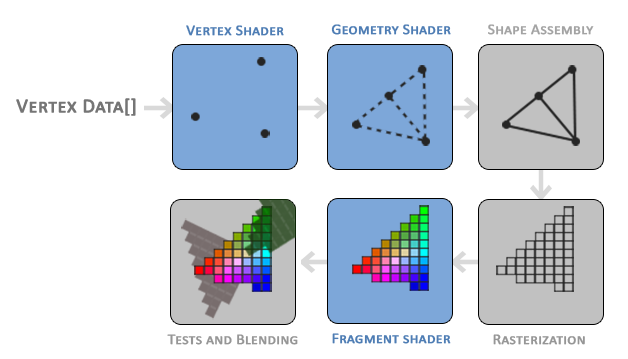
Shaders#
Shaders are short programs that render graphics data. As you can see from the previous image these programs run on different parts of the graphics pipeline. At this point in time we’re only going to be dealing with Vertex Shaders and Fragment Shaders also known as Pixel Shaders in some circles. We’re not going to touch Geometry Shaders as we don’t need them in this article.
A vertex is a computational representation of 3D space on a computer. Think of the cartesian coordinate system you learned of at school, but with an extra dimension called Z. So a typical vertex would be represented as { X = 100, Y = 50, Z = 200 }. Vertex shaders as the name implies does information transformation on the vertex information we initially pass in from the CPU. Vertex shaders are the first section of the pipeline that is done and can be altered, then that data is passed onto the fragment, so a fragment shader works on a singular vertex at a time.
Fragment shaders are programs that deal with the colouring of each pixel depending on the distance away from the vertex. I’II make this more explicitly clear in another article further down the line.
Initial Setup Of Project#
So this is the part of the article where we finally get to do some programming now that enough context has been given. This article assumes that you’ve gone away and followed the Moonworks setup article I’ve written up.
So with your nice new project setup I’m going to ask you to create a folder in there called Content and within there make another folder called Shaders this is where we’ll be saving our shader programs.
We’ll need the contents folder to be there along with the programs we compile in order for this program to work. So in csproj file copy the following xml in between the project section
<ItemGroup>
<Content Include="Content\**\*.*">
   <Link>Content\%(RecursiveDir)%(Filename)%(Extension)</Link>
   <CopyToOutputDirectory>PreserveNewest</CopyToOutputDirectory>
</Content>
</ItemGroup>
This will grab all of the files in the contents folder and copy it to the compiled executable section.
So in the setup article I really didn’t go too much into what the setting actually did in our main, so going to tackle that here.
var windowCreateInfo = new WindowCreateInfo(
     "Triangle Example Game",
     800,
     600,
     ScreenMode.Windowed
 );
So in our WindowCreateInfo, this class is used to create the window the program will live in.
- WindowTitle, a string which is simply the name that appears on the top of the game Window.
- WindowWidth, a unit that is the width of the window we want to create in pixels.
- WindowHeight, a unit that is the height of the window we want to create in pixels.
- ScreenMode, a enum with the values Window and Fullscreen, this decides if the game will just be a window that’ll take up a part of the screen or Fullscreen mode that renders the entire window on whatever is your default monitor is.
So next is framePacingSettings, this setting determines how many times a second an image will be displayed on screen.
So there are free settings that you can call in Moonworks to control the frame rate.
CreateUncapped, This will run the game as fast as possible Note that this may lead to overheating, resource starvation, etc. CreateCapped, This will run the game at a specific framerate. CreateLatencyOptimized, This will also run the game at a specified framerate, but it will also keep the frametime the same as well.
var framePacingSettings = FramePacingSettings.CreateLatencyOptimized(60);
This is the setting we’re going to be using for our project, if you want to use one of the other please feel free too.
So in our current settings we’ve set it so that only 60 images a second are displayed by the program. This is because the standard computer monitor and most televisions can only display 60 images a second. Some more modern monitors and televisions that can go up to 360 images a second are at this point in writing in the minority.
We then take the two settings we created above along with the AppInfo to give a Organization and Application name to create a new instance of a Game class we created for our project
var game = new BasicTriangleGame(
    new AppInfo("Triangle Example Game", "TriangleExampleGame"),
    windowCreateInfo,
    framePacingSettings);
Then we start the game up by calling this method
game.Run();
Shader Programming#
So as mentioned earlier in this article we need two shader programs in order to get a triangle up on the screen.
- Vertex Shader
- Fragment Shader
We’re going to use the shader programming language HLSL, which is Microsoft’s language. We’re using this language specifically because it’s the language mostly used in Moonworks examples, making it easier for you to go through the examples later on in your journey of learning Moonworks.
Vertex Shader#
Go into the Content Shader folder and create a new file called Vertex.vert.hlsl. Once you have that file created, open it up and write up the following code.
struct Input
{
    float2 Position : POSITION;
};
Struct Input is where the information from the CPU program is mapped to in the GPU program. float2 as the name suggests contains 2 floats in this specific context the x and y position of where the vertex point is going to be drawn onto screen. So the POSITION is a semantic tag that lets the GPU compiler / drivers know what sort of information it is.
struct Output
{
    float4 Position : SV_Position;
};
Struct output is where the position information is passed to the fragment shader.
Output main(Input input)
{
    Output output;
    output.Position = float4(input.Position, 0.0f, 1.0f);
    return output;
}
So what is happening here is we’re creating an output struct passing in the information we got originally from the CPU side of the game, setting the Z and W values and then passing that off to the fragment shader.
float4(input.Position, 0.0f, 1.0f);
The float datatype allows for some interesting and flexible component selection called swizzling. Swizzling allows us to use syntax like this:
float2 someFloat;
float4 differentFloat = someFloat.xyxx;
float3 anotherFloat = differentFloat.zyw;
float4 otherVec = someFloat.xxxx + anotherFloat.yxzy;
Another thing you may find that is odd instead of struct Output passing over a float2 the same value type we took into the Input just shaving off the third dimension or even a float3 with the limitation of only being allowed to work in 3D space we’re passing in a float4 (XYZW). Even more still while we assign the z value a 0.0f as expected, the W is assigned a 1.0f.
This shader takes the vertex data passed along from the CPU / RAM section as input, allows the program to alter it as needed and sends the output to be used for the graphics pipeline. As this is a simple program it pretty much does nothing besides just set the position of the vertex. The W value is used for something called perspective division, we won’t get too much into it here, but keep it in mind.
Fragment Shader#
Go into the Content Shader folder and create a new file called Color.frag.hlsl. Once you have that file created, open it up and write up the following code.
float4 main() : SV_Target0
{
    return float4(1.0f, 0.5f, 0.2f, 1.0f);
}
This shader just sets the color of each vertex to a specific color I set, which is a bright orange.
Compiling Shaders#
So go into the class you made that inherits from Game and add the following line in the class constructor.
ShaderCross.Initialize();
Not going into too much detail as to what shadercross is here, but the basic summary is that it’s a way to compile shaders across different graphics API types. If you a more detailed explanation then you can read the details here
then following that line add this section of code to compile the vertex shader we wrote earlier.
 var vertexShader = ShaderCross.Create(
     GraphicsDevice,
     RootTitleStorage,
     "Content/Shaders/Vertex.vert.hlsl",
     "main",
     ShaderCross.ShaderFormat.HLSL,
     ShaderStage.Vertex);
Then we’ll also add this too to compile the fragment shader we wrote.
  var fragmentShader = ShaderCross.Create(
      GraphicsDevice,
      RootTitleStorage,
      "Content/Shaders/Color.frag.hlsl",
      "main",
      ShaderCross.ShaderFormat.HLSL,
      ShaderStage.Fragment);
Going a bit more in depth of the variables being passed in order to create a shader we have.
- device / GraphicsDevice, this manages all graphics-related concerns. An instance of this is created in the game class.
- storage / RootTitleStorage, this Moonworks read only IO management class that is designed for portability..
- filepath / “Content/Shaders/Vertex.vert.hlsl”, this is the relative position of the file that needs to be compiled.
- entrypoint / “main”, is the entrypoint method of the method in the shader.
- shaderFormat / ShaderCross.ShaderFormat.HLSL, is what type of shader is being used.
- shaderStage / ShaderStage.Vertex is what stage of the shader this is.
So while I won’t go too much into detail here now, but there are ways of compiling shaders in advance and not during the runtime of the game as we’re doing here. Doing it during runtime isn’t always ideal and sometimes forbidden on some platforms.
Graphics Pipeline Creation#
In this section we’ll prepare how the information is going to go through the graphics pipeline.
[StructLayout(LayoutKind.Sequential)]
public struct PositionVertex(Vector2 position) : IVertexType
{
	public Vector2 Position = position;

	public static VertexElementFormat[] Formats =>
	[
    	VertexElementFormat.Float2
	];


	public static uint[] Offsets { get; } = [0];
}
This code stores and formats how we’re going to send vertex points across to the GPU. We’re storing them as Vector2 which represent 2D positions in space, on the X and Y Axis. We’re also using IVertexType, a Moonworks interface type that specifies what type is expected on the vertex shader end of the program, which in our instance is Float2. For now forget about offsets as we’re not using them in this article and the current value is just a default we’re passing along.
Now that we’ve set up the how and what data we’re sending to the GPU we need to actually set up the pipeline with this information and more, which I’II explain.
 var pipelineCreateInfo = new GraphicsPipelineCreateInfo
 {
 	TargetInfo = new GraphicsPipelineTargetInfo
    	{
        	ColorTargetDescriptions = [
            	new ColorTargetDescription
            	{
                	Format = MainWindow.SwapchainFormat,
                	BlendState = ColorTargetBlendState.Opaque
            	}
        	]
    	},
    	DepthStencilState = DepthStencilState.Disable,
    	MultisampleState = MultisampleState.None,
    	PrimitiveType = PrimitiveType.TriangleList,
    	RasterizerState = RasterizerState.CCW_CullNone,
    	VertexInputState = VertexInputState.Empty,
    	VertexShader = vertexShader,
    	FragmentShader = fragmentShader
 };
There is a lot going on here and to keep this article on track I’m just going to address variables that are immediately relevant to our purposes.
Format = MainWindow.SwapchainFormat,
Format sets up how the colour information is to be interpreted on a per pixel basis. By default Moonworks uses B8G8R8A8Unorm, which is Blue 8bits, Green 8bits Red 8 bits and Alpha bits.
PrimitiveType = PrimitiveType.TriangleList,
PrimitiveType sets up what is the base shape the objects will be made out of. As I mentioned earlier the default choice is a triangle.
RasterizerState = RasterizerState.CCW_CullNone,
RasterizerState describes in what order the vertices will be rendered based on how they are sent in either clockwise or counterclockwise. It also decides if vertices will not be displayed based on a condition, not displaying them on that condition being called culling. In this case we’re doing counter clockwise and no culling.
VertexShader = vertexShader,
FragmentShader = fragmentShader
Finally we need to at minimum assign a vertex and fragment shader as these are the bare necessities of a graphics program.
pipelineCreateInfo.VertexInputState = VertexInputState.CreateSingleBinding<PositionVertex>();
This is where we bind the description of the vertex struct on the CPU side with the description on the GPU side.
Finally you actually create the pipeline you want to send through. Start off with creating an instance of the pipeline near the top of the class
private readonly GraphicsPipeline _pipeline;
Then just after that assign that pipeline
_pipeline = GraphicsPipeline.Create(GraphicsDevice, pipelineCreateInfo);
This will actually create the pipeline that will be used in the duration of this program.
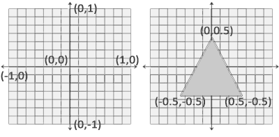
Normalized Device Coordinates (NDC)#
Normalized device coordinates is a small space where the x, y and z values go from the range of -1.0 to 1.0. Any coordinates that fall outside that range will be discarded / clipped and won’t be visible on your screen.
Unlike usual screen coordinates the positive y-axis points in the up-direction and the (0, 0) coordinates are at the centre of the graph, instead of the top left.
Sending The Information Across#
At this point we’ve got the pipeline created and ready and all we need to do is send the data across to the memory accessed by the GPU to be ready to draw the triangle.
We start off by creating the points of the triangle we want to create.
 ReadOnlySpan<PositionVertex> vertexData = [
	new PositionVertex(new Vector2(-0.5f, -0.5f)),
	new PositionVertex(new Vector2(0.5f, -0.5f)),
	new PositionVertex(new Vector2(0.0f, 0.5f))
 ];
So here we’re just placing a point at the top middle centre of the screen and then at the bottom middle left and right as you can see from the previous section about Normalized Device Coordinates.
private readonly Buffer _vertexBuffer;
We then create a buffer to store that information, create a new buffer
 var resourceUploader = new ResourceUploader(GraphicsDevice);
 _vertexBuffer = resourceUploader.CreateBuffer(vertexData, BufferUsageFlags.Vertex);
Then create an uploader and initialize the buffer to be uploaded to the VRAM.
  resourceUploader.Upload();
  resourceUploader.Dispose();
We then can upload the data now and then destroy the uploader as we’re not using it anymore
Drawing The Triangle#
So in the drawer method you’ll need to write in the following code
var cmdbuf = GraphicsDevice.AcquireCommandBuffer();
The commander buffer is the class you use to submit your actual information to be processed by the GPU. Here we’re just getting the default one that is created when you initialize your project from the Graphics Device.
var swapchainTexture = cmdbuf.AcquireSwapchainTexture(MainWindow);
So how things are actually drawn is that you have 2 textures, a texture being a buffer of pixels. You have one texture that you draw pixels onto and the other that you actually display. So in our case one of the textures will be displayed for 16.67ms and then the other texture we were drawing on will then be displayed and the one that was taken down will be the new one we draw on.
if (swapchainTexture != null)
{
}
We specifically check to see if there is actually a texture currently free to draw on as there is a real possibility that there isn’t one currently available and the GPU are two different sections of your machine and they don’t perfectly line up with each other.
 var renderPass = cmdbuf.BeginRenderPass(
     new ColorTargetInfo(swapchainTexture, Color.Black)
 );
We put this section of code inside the swapchainTexture null check block. This is doing two jobs firstly it is setting the default colour of the swapchainTexture, in our case black. It is also creating the renderPass object which is the actual class that we use to set the drawing as you’ll see.
renderPass.BindGraphicsPipeline(_pipeline);
Here we’re just binding the graphics pipeline we created earlier in the article with the current render we’re doing.
renderPass.BindVertexBuffers(_vertexBuffer);
Here we’re binding the vertex information we created earlier to the pass too
renderPass.DrawPrimitives(3, 1, 0, 0);
Here we’re actually drawing the triangle. We’re passing the number of vertices to which we’re drawing 3, we then pass on how many instances of the object we’re drawing which is just 1 and finally the where is the first vertex and instance is both of which is set at 0.
cmdbuf.EndRenderPass(renderPass);
Finally we use the command buffer we created earlier to submit the render pass.
GraphicsDevice.Submit(cmdbuf);
This is outside the swapchainTexture null check block. Finally finally once that’s all done all we need to do is submit the command buffer itself via the Graphics Device.
So hopefully after all that hard work you’ve gotten yourself a nice little orange triangle up on your screen. If that isn’t the case you can look at my example that I threw up which is here. If that doesn’t work then maybe drop a line in the discord server which you can find here I usually hang out there